Home//Products//Trench Covers: Solid, Grated and Bolted//Installation Instructions
Trench Casting Installation Instructions
For those who are not experienced in the installation of Deeter drainage structures (3990 or 3990-AB Series), the following procedures are one method of achieving desirable results.
Forming Procedures, Non-Bolted Units
Materials
Under normal situations, use 3/4 inch plywood for forming walls. 2’x4's are suitable for studs, plates, bracing and spreaders. A typical installation is shown in Figure 1a. Details and suggestions are based on using the Deeter Foundry Type ‘X’ frame.
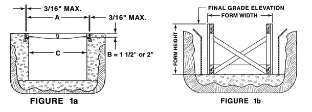
Pour the trench bottom to the proper depth and slope and allow curing time. Construct the forms. For properly fitting covers, the forms must be PLUMB, STRAIGHT, LEVEL and SOLID. The width of the forms (see Figure 1b) establishes the trench wall. This dimension must correspond with the “C” dimension on catalog page 170 and (Figure 1a). The top of the form (see Figure 1b) corresponds to the final grade elevation when installing non-bolted frame and grates/lids. Spreaders are installed, extending them beyond the edge of the form, to provide a stop for the wood, seat forms (see Figure 2 and 3).
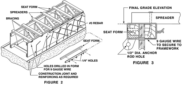
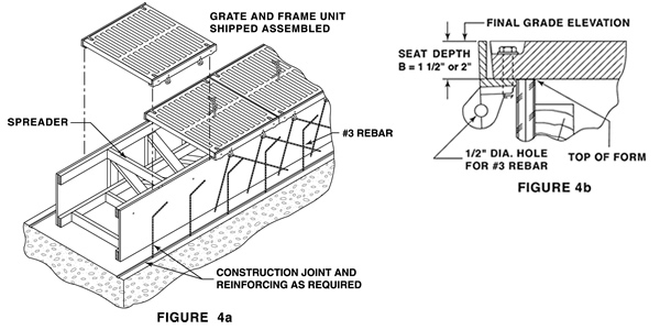
Cut the wood, seat forms to the exact inside horizontal and vertical dimension of the iron, frame seat (Note: all Deeter frames have a slight radius at the corner of the seat and vertical face of the iron, frame sections so the wood, seat form, pieces should be beveled to accommodate this radius). The wood, seat form is nailed flush to the top of the form walls and the iron, frame pieces are nailed to the wood, seat forms through the holes provided in the side wall of the iron, frame sections. In proper orientation, the anchor lugs on the iron, frame pieces are positioned downward. Iron frame sections should be butted together snuggly, leaving as little gap as possible. The iron, frame seat form and plywood sides of the form are then secured with 9 gauge tie wire tied through a drilled hole in the plywood side wall (see Figure 3). Number 3 rebar can be installed through the anchor holes provided on the iron frames.
Check measurements. The grate/lid opening dimension must correspond to the “A” dimension on catalog page 170 plus 3/16” maximum per side (see Figure 1a and 3).
Pour concrete using the top edge of the iron frame pieces as a final elevation guide. Strip forms after concrete is properly cured.
FORMING PROCEDURES, BOLTED TRENCH
Materials
Under normal situations, use 3/4 inch plywood for forming walls. 2’x4's are suitable for studs, plates, bracing and spreaders. A typical installation is shown in Figure 1a. Details and suggestions are based on using the Deeter Foundry Type "X" frame.
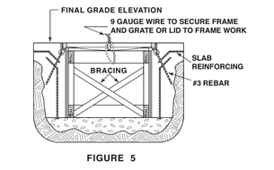
Bolted frames and grates/lids are furnished assembled (see Figure 4a), and therefore require appropriate forming procedures. AT NO TIME SHOULD THE UNITS BE DISASSEMBLED DURING INSTALLATION! VERIFY THAT THE 3/16” PER SIDE MAXIMUM GAP BETWEEN FRAME AND LID HAS NOT CHANGED DURING TRANSPORT. WHEN SATISFIED THE GAP IS CORRECT, TORQUE BOLTS TO ASSURE THE PIECES REMAIN IN THAT ORIENTATION.
Pour the trench bottom to the proper depth and slope and allow curing time. Construct the forms per Figure 4a. For properly fitting covers, the forms must be PLUMB, STRAIGHT, LEVEL and SOLID. The width of the forms establishes the trench wall. This dimension must correspond with the “C” dimension on catalog page 170 and Figure 1a.
Construct the forms (see Figure 4a). The grate/lid top surface establishes the final grade elevation when the assembled iron casting unit is set on the form (see Figure 4b). Accordingly, form side wall elevation is set at final grade elevation less the seat depth “B” dimension.
(Note: “B” dimensions vary per catalog number. Deeter recommends checking dimensions on the catalog line item of page 170. If unsure, contact product engineering or your Deeter representative).
Set frame and grate/lid assembled sections on the forms, taking care to keep the sections tight to one another to eliminate creep. When the sections
are in the proper position, wire them to the bracing as show (see Figure 5). Number 3 rebar can be installed through the anchor holes provided on
the iron frames.
Check measurements. The grate/lid opening dimension must correspond to the “A” dimension on catalog page 170 plus 3/16” maximum per side (see
Figure 1a).
Pour concrete using the top edge of the iron frame pieces as a final elevation guide. When concrete is properly cured, unbolt and remove grates/lids, retaining their position and orientation. GRATES/LIDS MUST BE REINSTALLED IN THE EXACT WAY THEY CAME OUT TO ASSURE PROPER BOLTHOLE ALIGNMENT. DO NOT ALLOW DEBRIS TO FALL INTO THE FRAME BOLTHOLES AS IT MAY PROHIBIT PROPER TIGHTENING OF BOLTS. Strip forms and replace grates/lids in the same location and orientation as they came out. Reinstall bolts, tightening them to the specifiers desired torque. The completed installation should resemble Figure 1a.
General Comments for Non-bolted and Bolted Applications
All frame sections are manufactured and furnished in standard lengths. It is the responsibility of the installer to cut frame pieces to the proper length and miter corners where applicable. In cases where trench direction must change, special drawings can be furnished by our Product Engineering Department. These prints will show special lengths and cuts of grates/lids, and other essential information.